gantt
    title Bachelor Degree Tasks
    dateFormat  DD-MM
    axisFormat  %d-%m
    tickInterval 1week
    weekday monday

    Start of the Thesis : milestone, start, 15-07, 0m
	Quansar qube Servo 3:qube3, 15-07,01-08
	Q2:q2, 01-08,16-09


	section Construction
	Prototyp v0 :prot,after start,3d
	Motormount:motor,01-08,1d
	Sketch v1:sketch,01-08,1d
	Aluminium Frame:alu,05-08,5d


	section Interfacting <br> with Quarc
	Basic HIL undrestanding:basichil,after prot, 2d
	UDP bridge Python :upd, after basichil,2d
	Serial communication bridge Python:Serialcommunication,after upd,1d
	Finding the limits of Q2:limitsq2,02-08,1d

	section Electronics
	Hardware signal processing:hsp,after Serialcommunication,1d
	Schmitt trigger :schmitt, after fft,1d

	section Code
	Magnet :magnet, after hsp,1d
	Serial:serial,after magnet,1d
	Concurrency:concurrency, after serial,3d
	FFT:fft,after concurrency,3d


    section Control
    Research:research,12-08,3d
    Modeling:modeling,after research,4d
    Identificationg:identification,after modeling,1d
    Control:control,after identification,3d

	section Document
	Writing :writing, after control, 12d
    Proofreading: proofreading, after writing, 3d

End of the Thesis : milestone, end, 16-09, 0m
Host PC
user:.\adminpassword:Admin.21
External Communication
it’s wrong: here.
trying out Instrument Control Toolbox was a fail.
Trying out lots of serial stuff not working.
Getting it to work with udp.
How dose the data get transferred?
The data can get transferred as a double. For a quick check: calculating a double
On how this is really done: wikipedia.
Python UDP
With Python I can read the com port and send it to a quarc stream server UDP block with the option peer=any.
Python
import serialimport socketimport timeimport struct# Serial port configurationserial_port = 'COM8' # Change this to your serial portbaud_rate = 115200 # Set the baud rate according to your device# UDP configurationudp_ip = 'localhost'udp_port = 12345#udp_port= 52850# Open serial portser = serial.Serial(serial_port, baud_rate, timeout=1)# Create a UDP socketsock = socket.socket(socket.AF_INET, socket.SOCK_DGRAM)#sock.bind((udp_ip, udp_port))#while True:# Receive a response from the server # data, server = sock.recvfrom(0) # print(f"Received response from server: {data.decode()}")t= True# Raw byte sequenceraw_bytes = b'\xe0\xd6\xdd<\xd5!\t@'# Convert the raw byte sequence to a doubledouble_value = struct.unpack('d', raw_bytes)[0]print(f"Raw bytes: {raw_bytes}")print(f"Double value: {double_value}")try: while True: # Read data from serial port serial_data = ser.readline() decoded_str = serial_data.decode('utf-8') cleaned_str = decoded_str.strip() #print(cleaned_str) # Hexadecimal string #hex_string = "01000000000000f0bf # data=0 # if t: # data=struct.pack(f'<d', 1.234) # #hex_string = "01000000000000f0bf" # t=False # else: # #hex_string= "01000000000000f0bf" # data=struct.pack(f'<d',2*3.14152) # t=True # Convert the hexadecimal string to bytes #data = bytes.fromhex(hex_string) #print(data) #serial_data=data serial_data=struct.pack(f'<d',float(cleaned_str)) if serial_data: sock.sendto(serial_data, (udp_ip, udp_port)) #sock.recvfrom(serial_data, (udp_ip, udp_port)) print(float(cleaned_str)) #time.sleep(1)except KeyboardInterrupt: print("Terminating...")finally: # Close the serial port and socket #ser.close() sock.close()
I used com0com to create a virtual com port pair. I open a stream client on one of the serial ports. I doesn’t matter what flow control I have. It works flawlessly. It is working with Blocking and in non Blocking mode. The client is to com port 9 e.g. and I use still open com port 9 in python.
using python to send data
import serialimport structimport timevalue=3.141592while True: # Define the raw bytes # Pi = 0x400921FAFC8B007A #04 is the MSB here sign is 0 and exponent is 100 0000 0000 # Most accurate representation = 3.14159200000000016217427400989E0 raw_bytes = struct.pack('>d', value) #little endian # Print the raw bytes in hexadecimal format hex_representation = ' '.join(f'0x{byte:02X}' for byte in raw_bytes) print(hex_representation) # Open serial port 8 ser = serial.Serial('COM10', baudrate=115200, timeout=1) # Write the bytes to the serial port in reverse order for byte in reversed(raw_bytes): ser.write(byte.to_bytes(1, 'little')) time.sleep(1) # Close the serial port ser.close() value=-1*value
script for working communication
script for working communication
import serialimport structprint("nothing gets printed into the output it's still running (ctrl+c to stop)")quarc='COM9'sensor='COM21'SenSer = serial.Serial(sensor, baudrate=115200, timeout=0.1)QuaSer = serial.Serial(quarc, baudrate=115200, timeout=0.1)SenSer.flush()QuaSer.flush()recieve=-1oldSensor=0oldQuarc=0# in case we do bytes remove the and 0while 10000<recieve or recieve<1 and 0: if SenSer.readable(): notused=SenSer.read() print("reading a byte") rec_bytesS=SenSer.read(8) recieve=struct.unpack('<d', rec_bytesS)[0]while True: #SenSer.read_all() #rec_bytesS=SenSer.read(8) #print(f'recieving {struct.unpack('<d', rec_bytesS)[0]}') #print(rec_bytesS) if SenSer.readable(): line=SenSer.readline() string=(line.decode('utf-8')) try: number=float(string) if number!=oldSensor: oldSensor=number print(f'from sensor to quarc:{oldSensor}') QuaSer.write(struct.pack('<d',oldSensor)) except (UnicodeDecodeError, ValueError) as e: # Handle decoding errors and conversion errors #print(f"Error during conversion: {e}") pass QuaSer.read_all() rec_bytesQ=QuaSer.read(8) qdouble=struct.unpack('<d', rec_bytesQ)[0] if qdouble!=oldQuarc: oldQuarc=qdouble tosend=str(qdouble)+'\r' if SenSer.writable(): SenSer.write(tosend.encode('utf-8')) print(f'from quarc to sensor:{qdouble}') #double_value = struct.unpack('<d', rec_bytesS)[0] #print(rec_bytesQ) #print(double_value) #for byte in (rec_bytesQ): # for doing stuff directly: #ser.write(byte.to_bytes(1,'big')) #big endian means we read the first and send the first it is actually not big endian #for byte in (rec_bytes): # for doing stuff directly: #serSensor.write(byte.to_bytes(1,'big')) #big endian means we read the first and send the first it is actually not big endian
Describing the Problem
The problem is that I transfer 8 bytes of data over serial and I cannot tell the beginning of the 8bytes to form a double.
So it is not easy to just get a double form your serial connection on arduino.
This does not work and gives weird numbers.
link
here link
go to quarc 2024 installer and documentation
read the docs and install quarc 2024 installer
visual studio community 2022: c++ windwows apps, .net runtime. Both will be 11.3gb total
Install matlab coder and Simulink coder
%https://www.thingiverse.com/thing:1361044% ratio = incoming speed / outgoing speed = (R + S) / S => R = (ratio - 1) * S %P = (R - S) / 2 = whole numberclose all; clear all; clc maxwheels=200;R=1:maxwheels;S= 1:maxwheels;% Loop over each S and ratio to find valid R and Pindex=1;for rloop = R for sloop = S P=(R(rloop)-S(sloop))/2; % Check if P is a whole number if mod(P, 1) == 0 data(index,1)=R(rloop); data(index,2)=S(sloop); data(index,3)=P; data(index,4)=(R(rloop)+S(sloop))/S(sloop); index=index+1; end endendminratio=9;maxratio=11;minWheelSize=12;maxWheelSize=200;wheelchecker=data(:,1)>minWheelSize&data(:,1)<maxWheelSize&data(:,2)>minWheelSize&data(:,2)<maxWheelSize&data(:,3)>minWheelSize&data(:,3)<=maxWheelSizedata(data(:,4)>minratio&data(:,4)<maxratio&wheelchecker,:)
The voltage generator is a Traco Power TEC 3-1223. The datasheet can be seen here.
OPAMP
The opamp we use is a low noise fet op amp from TI. The datasheet can be seen here.
NPN Transistor
The BC141-16 transistor is used to control the power to the magnet. The datasheet can be seen here.
MUX
here.
It is not possible to use a comparator to generate a digital signal of stings output to get the frequenzy of the string. In order to use FFT we need real measurements.
edit hardware.drawio
It is important to choose a proper value for the f_egg.
bad example with 100n and 1k rc.
Using RC with 1μF and 220Ω.
f=2∗π∗220∗1μ1=730Hz .
This is dampening the signal a lot. It is required to adjust the Schmitt trigger.
I adjusted the Schmitt trigger by changing the 1k to 220.
Magnet
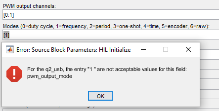
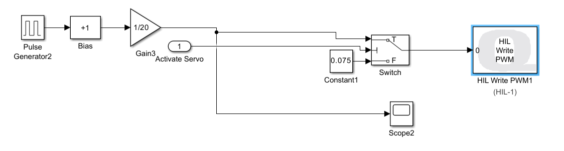
It is not possible control the duty cycle of one pwm with a fixed frequency and contorl the other with a fixed duty cycle but varying frequency.
This means the MCU has to output a PWM frequency with varying frequency.
MCU
data acquisition
The thing about fft is that it taks as long as you want your accuracy. If I want to be able to detect and destinglish between frequencies like 300Hz and 301Hz I have to sample for 1 second which is the delta.
Instead of doing the FFT There is the option to do Zero crossing detection.
ADC in general
Testing the ADC of the ESP32
while (1){ Serial.println(analogRead(analogPin)); Serial.println(micros());}
On the left the data can be plotted over time. This corresponds to the actual data taken with an oscilloscope. The figure on the right shows the time difference between samples. It seems that the 8 samples only take 172μs and then one takes 10ms.
Maybe it is a problem with the serial output. We can toggle the pin of a led and see the output with an oscilloscope.
while (1){ analogRead(analogPin); digitalWrite(led, on); on = !on;}
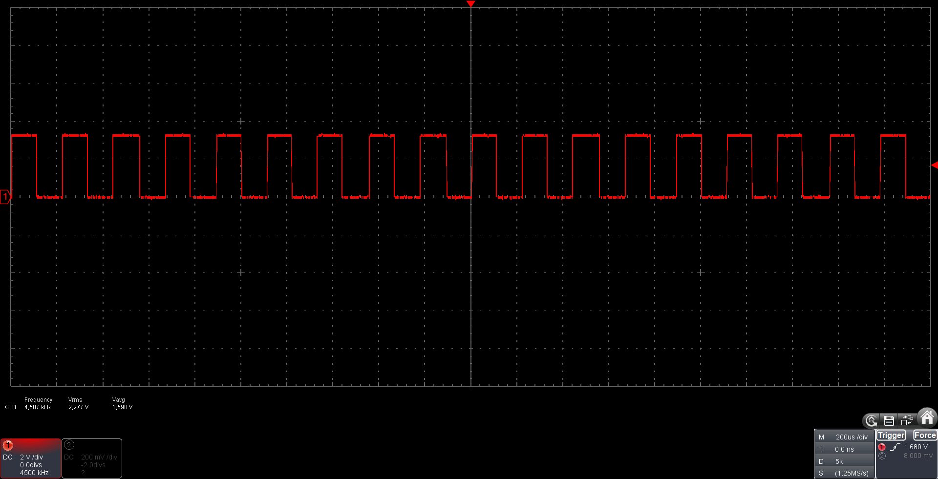
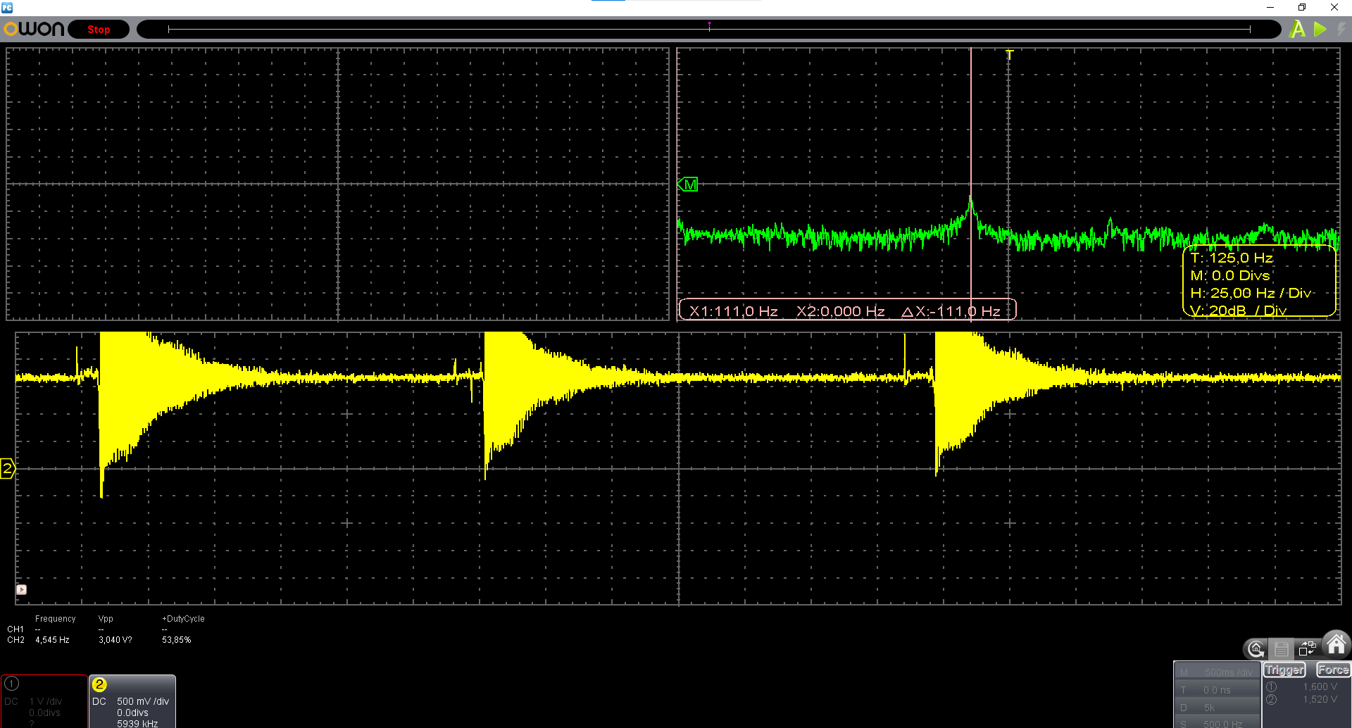
The adc seems to be working fine. Here with a sampling frequency of 4500Hz
All images like this are taken with my Oscilloscope.
Timing
The phone reports a frequency of 103Hz.
The data from the adc gives us a frequncy of 104.8Hz
The oscilospoce returns a frequency of roughly 103Hz.
interestingly there was no differenc between readanalog and readanalog raw.
With adc1_get_raw(ADC1_CHANNEL_0); I was able to get a sampling rate of 11750Hz.
The main code is esp32main.cpp.
ADC of the STM32401CCU
The ADC of the STM32F401ccu is faster. A sampling rate of up to 16000Hz can be achieved. There seems to be a problem with the ADC. Nothing below the average can get sampled.
code stm32main.cpp.
ADC on the Arduino UNO
The sampling time of 110us can be achieved.
Closing the control loop
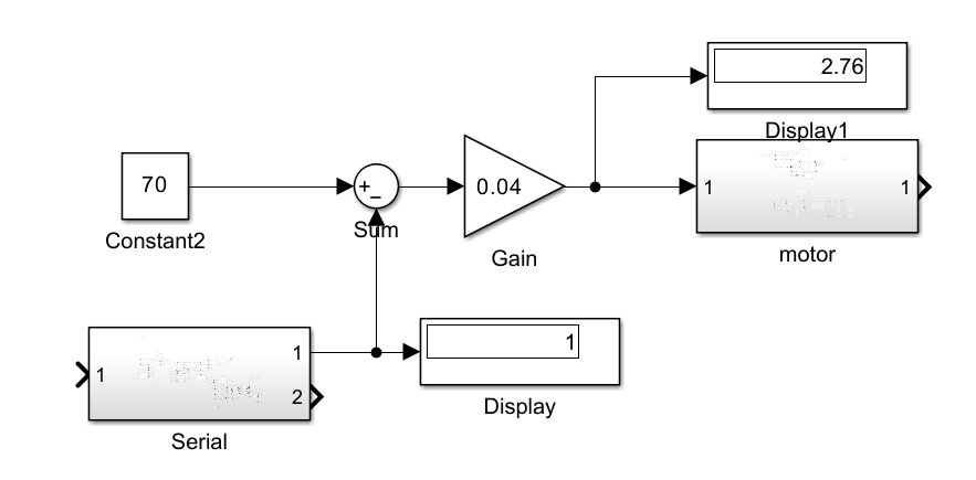
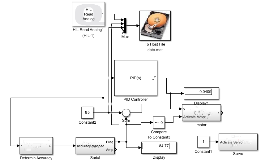
For the beginning we take an easy P controller with the gain of 0.04.
Hopefully last notes on 2024-08-27.
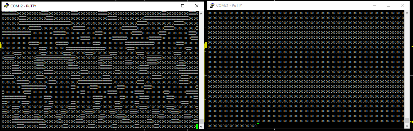
data transmission through serial1 with rx to tx connected and using just PA9 to transmit with 115200 baud.
There is no 12V connceted.
On the right we can see the data transmission of the RX/TX signal to a USB uart converter.
On the left we can see the data of my pcb at the same time. The CH340C is configured correctly.
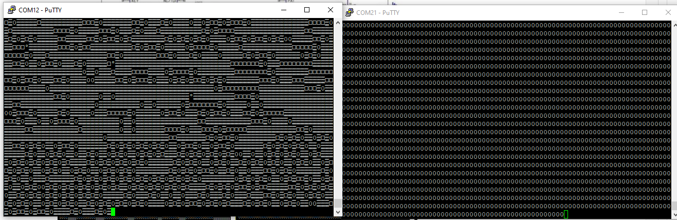
It is only transferring with 3.3 logic even though VUSB is 5V.
With the 12V connected the signal gets even more garbled and almost indistinguishable from the noise.
see the datasheeht. 6.2. Electrical Parameter clearly states that if you don’t have V3 connected to Vcc it is not in spec and it needs 5V to function for Vcc. I soldered a bridge between Vcc and V3. It didn’t help.
I later realized that I only soldered a big cap for Vcc that was on the other side of the board. Luckily I had a cap planned next to the CH340C which I didn’t use earlier because my thought was now that V3 is connected it is also connected to the big Cap on the other side. After connecting a 104μF Cap right next to the CH340C it works better almost flawlessly. The stm32 chip warmed up and died.
After some seconds the MCU got super hot and died.
The usart to USB bridge also died. There is a ground VCC residence of 0 ohm for it.
Signal Acquisition
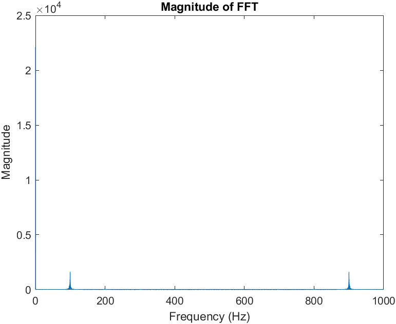
First 100Hz (eyeballed) signal sampled with 1000Hz. 100.mat.
Other Measurements:110.mat peak at 109.997Hz and 111.mat.
Setting the Frequency with the Oszi.
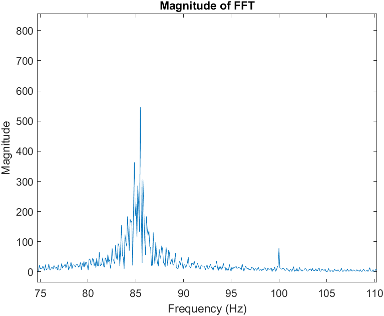
load('100.mat')data= data(2,:);plot(data)% Sampling frequency (replace with your actual sampling frequency)Fs = 1000;% Compute the FFTY = fft(data);% Number of data pointsn = length(data);% Compute the frequency axisf = (0:n-1)*(Fs/n);% Plot the FFTmagnitudeY = abs(Y);plot(f, magnitudeY);xlabel('Frequency (Hz)');ylabel('Magnitude');title('Magnitude of FFT');
It is very hard to really the correct frequency visually on the oszi. After Analyzing 111.mat it shows that the frequency was actually 111.3Hz.
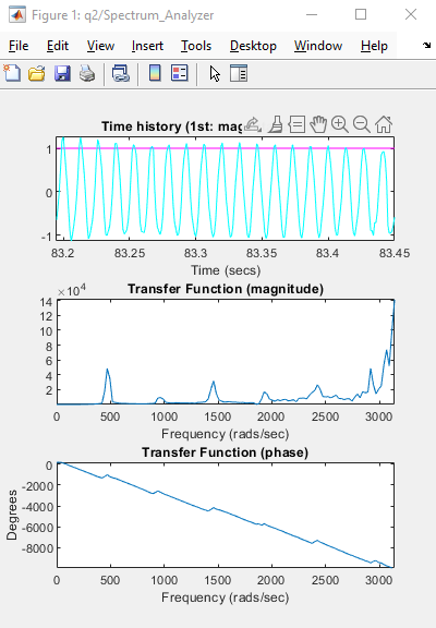
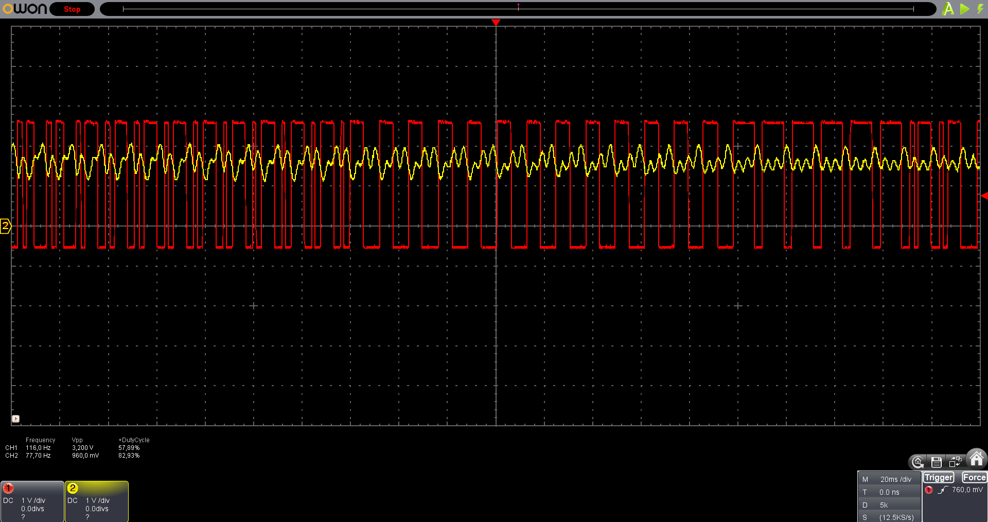
Testing the Control loop
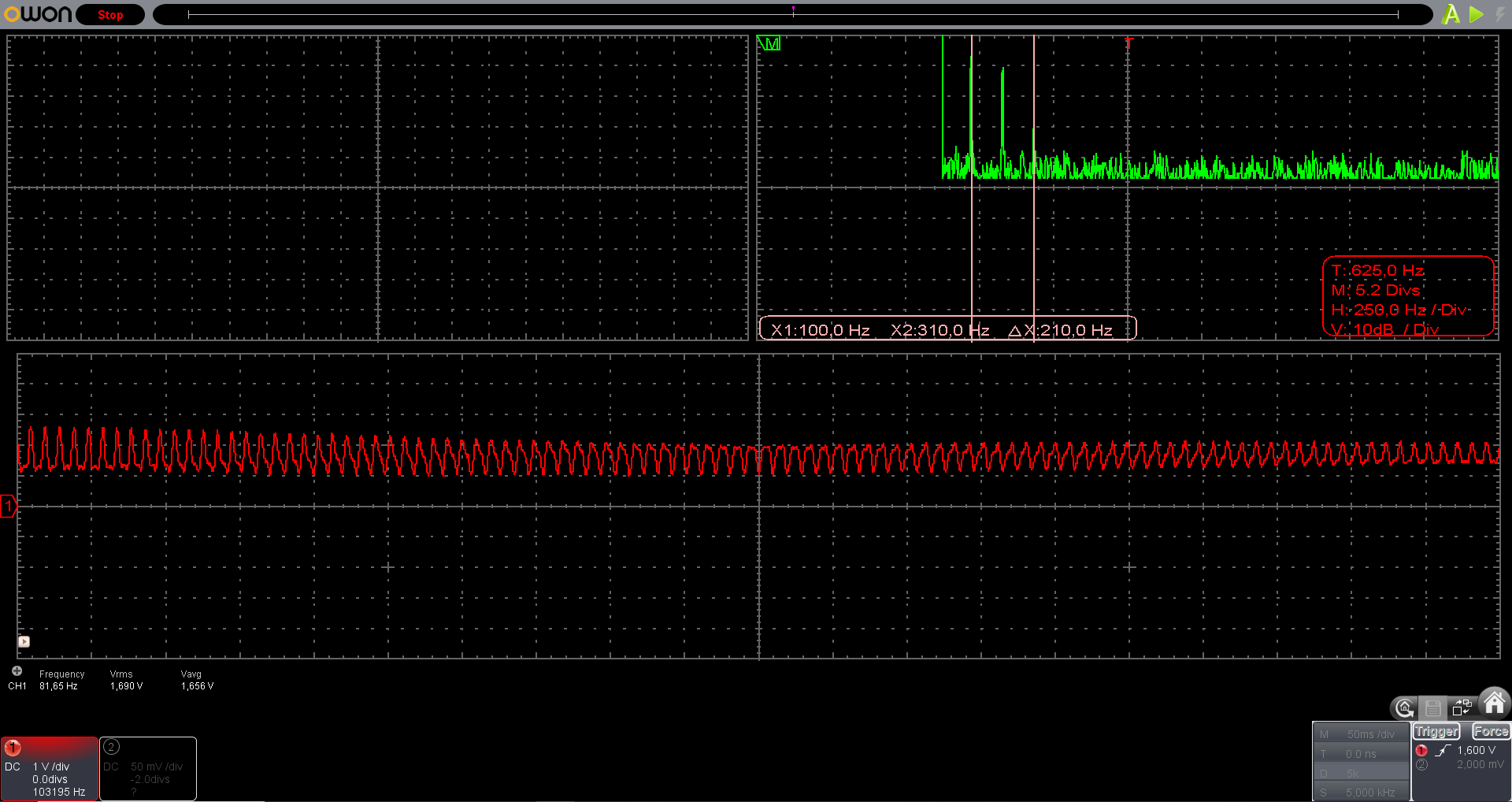
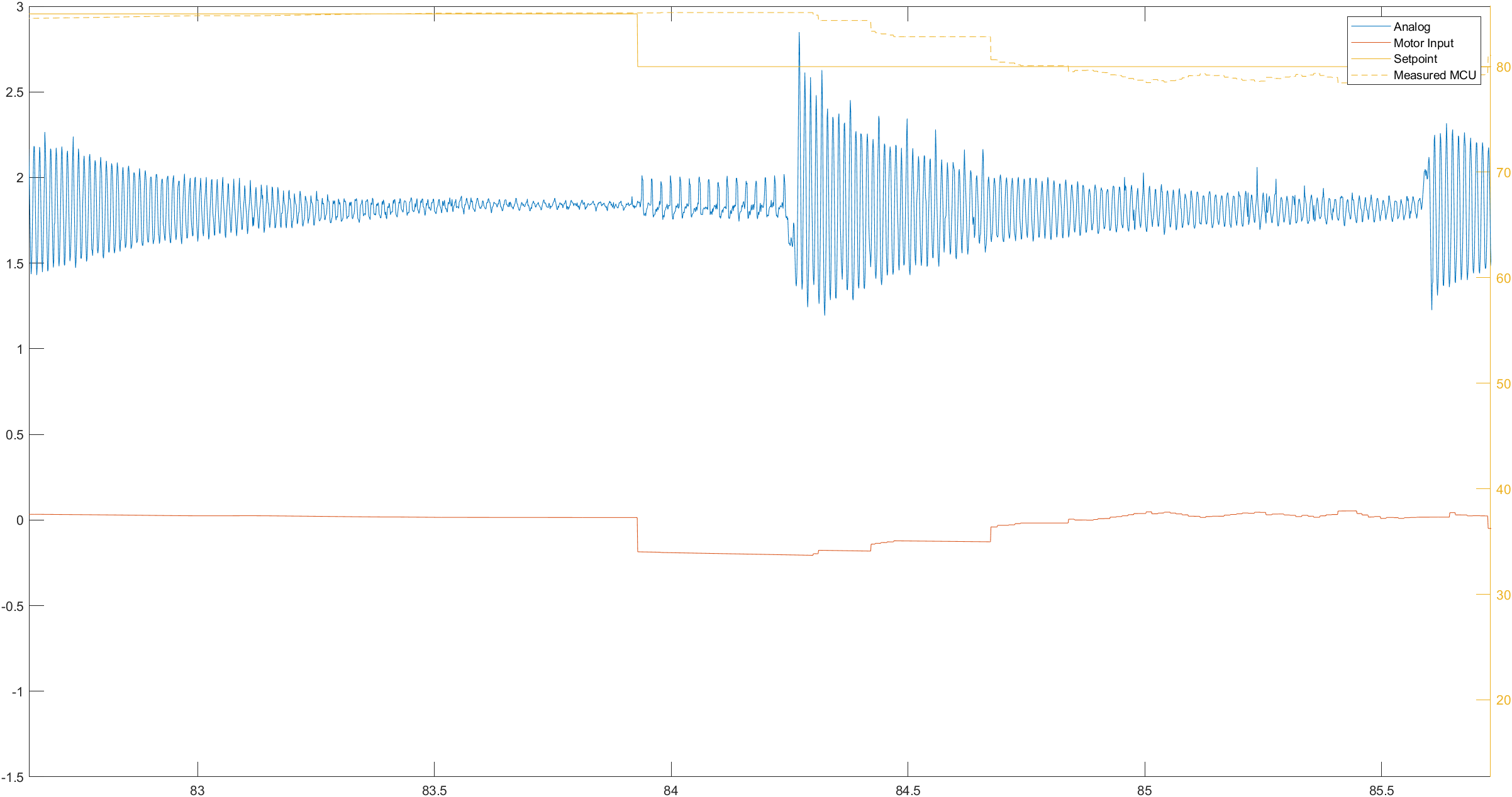
On analog channel 1 there we get the adjusted signal of the pickup sensor.
Data is available 85to80to85_analog_freq_setpoint.mat.
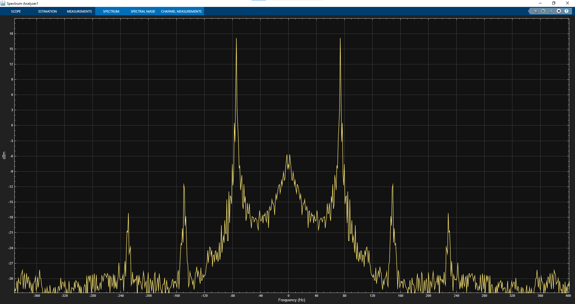
Using the Vaules after 35s. We can do the FFT like we did in Signal Acquisition.
Next to the roughly correct 85Hz signal we have a peaks at 50Hz and at multiples of it.
After the setpoint change in 26.4 the motor seems to take some time to respond.
The motor kicks in immediately as shown below.
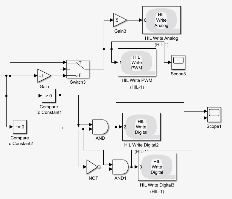
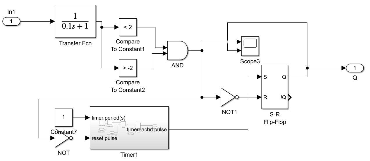
The ‘Determin Accuracy’ block is used to check if the error is in between ±1 . If so we use a PT-1 to smoothen our sensor Signal to get an average. There are no models used to adjust the control parameters yet. The Motor is not position controlled yet.
Motor
19 revolutions of the peg is one revolution of the cylinder.
Position control drive side
The position control of the Motor on the drive side is fairly easy and accurate. With a simple PI controller it is possible to get an accuracy down to below 2/9600 of a revolution. This is not very useful. There is a lot of uncertainty on the output side.
2024-08-16 breaking of string ‘1’ E.
Position control of output side
Hardware: Series ETA25PS.
Mount:
Let’s try to contorl the motor positon to the 1000th of a rotation. As you can see in Testing the Control loop there seems to be 50Hz noise on all lines. The noise here visible is not this noise it is vibration of the engine. I tried to get rid of the vibration. Nor P nor d nor I on it’s own were without vibration. This concludes that the vibration has to be taken into account. Dampeners??
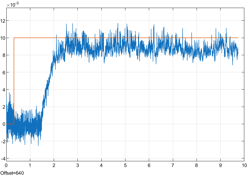
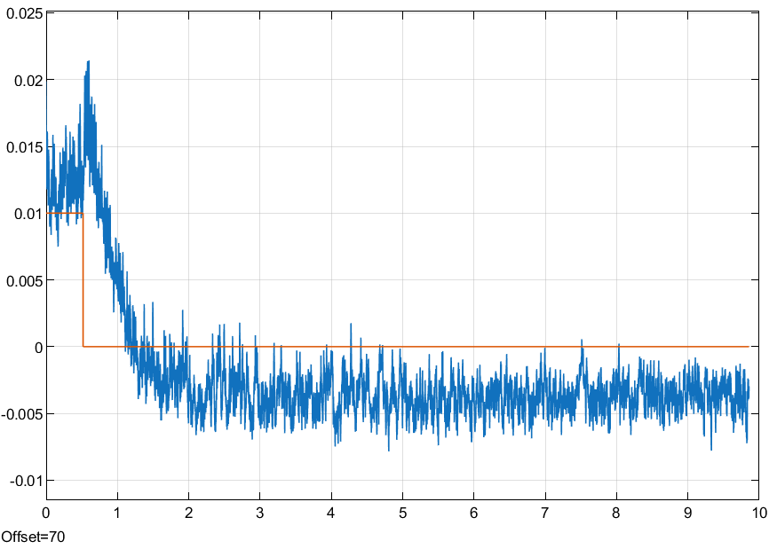
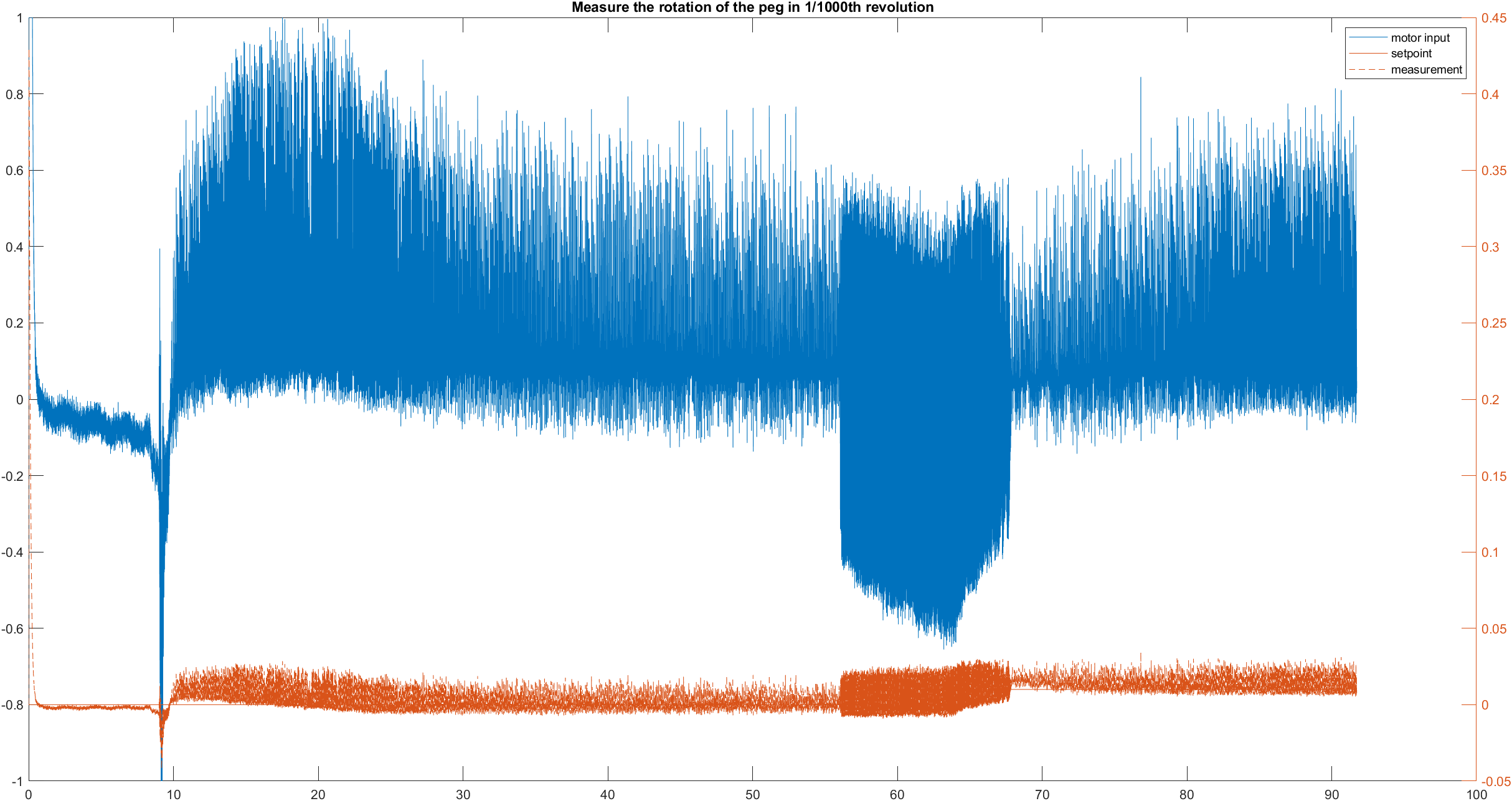
Jump from 0 to 100010 of a Revolution. The position contorl is stationary accurate!
Using a friction compesition is working. It is easier to just add a D part to the controller so the Motor is in movement most of the time. Friction is now negligible.
Serial is working but very unreliable. Screenshot explained
todo:
magnet anschliessen
und motor
platine löten
 spectrum analyzer DSP Toolbox

 drawio file : bachelor_overview_control.drawio

 edit hardware.drawio
It is important to choose a proper value for the f_egg.
bad example with 100n and 1k rc.
edit hardware.drawio
It is important to choose a proper value for the f_egg.
bad example with 100n and 1k rc.
 Using RC with and .
.
This is dampening the signal a lot. It is required to adjust the Schmitt trigger.
I adjusted the Schmitt trigger by changing the 1k to 220.
Using RC with and .
.
This is dampening the signal a lot. It is required to adjust the Schmitt trigger.
I adjusted the Schmitt trigger by changing the 1k to 220.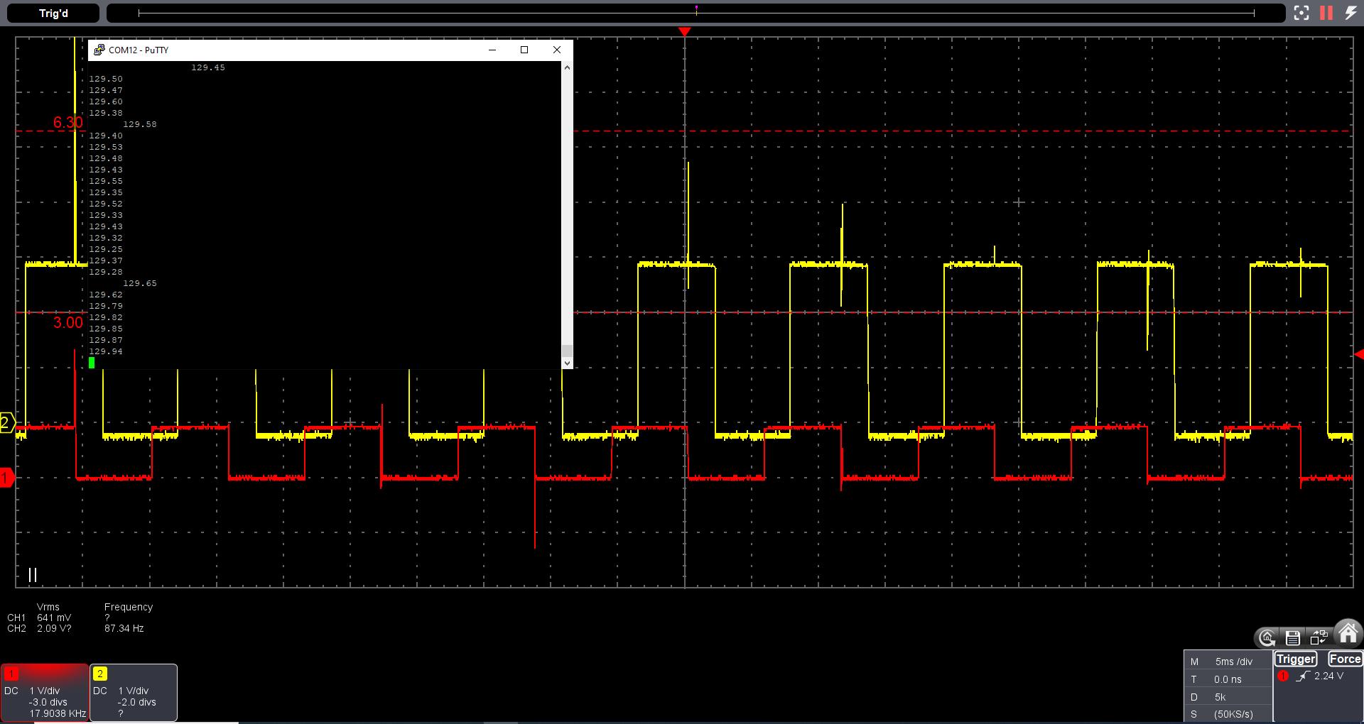
 This means the MCU has to output a PWM frequency with varying frequency.
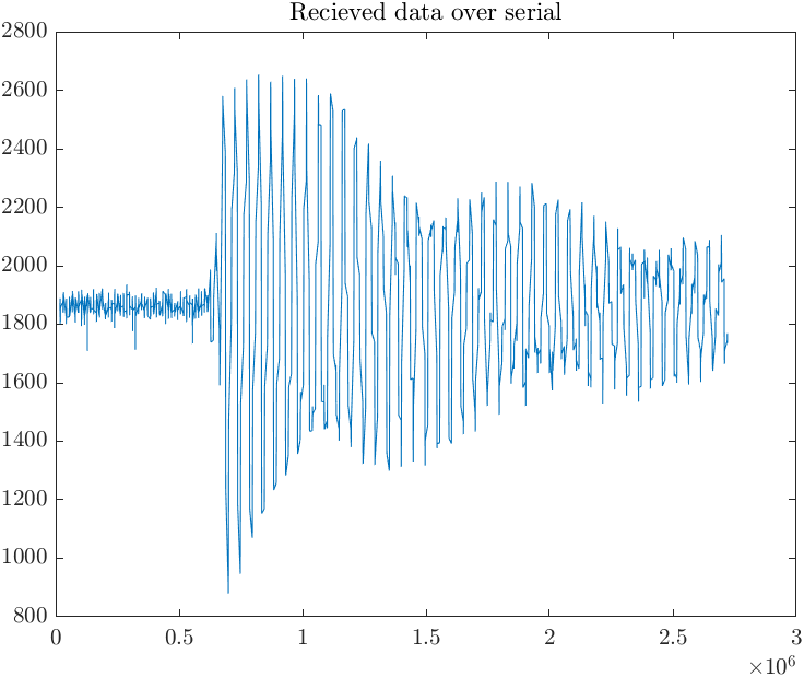

 All images like this are taken with my Oscilloscope.
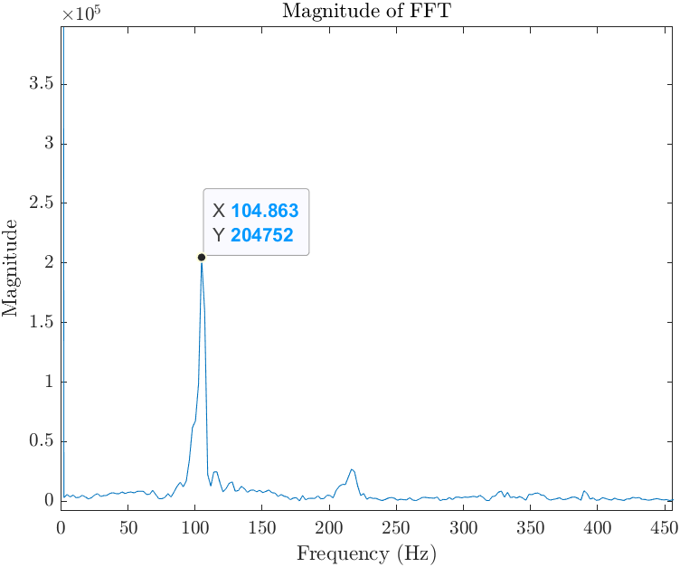

 designed on 2024-08-14 and 2024-08-15. Delivered on 2024-08-22.
The files of both pcbs can be found here: easyeda_bachelor_hardware_2024-09-13.epro.
designed on 2024-08-14 and 2024-08-15. Delivered on 2024-08-22.
The files of both pcbs can be found here: easyeda_bachelor_hardware_2024-09-13.epro.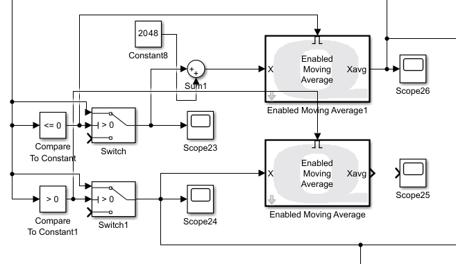
 Hopefully last notes on 2024-08-27.
data transmission through serial1 with rx to tx connected and using just PA9 to transmit with 115200 baud.
Hopefully last notes on 2024-08-27.
data transmission through serial1 with rx to tx connected and using just PA9 to transmit with 115200 baud.
 There is no 12V connceted.
On the right we can see the data transmission of the RX/TX signal to a USB uart converter.
On the left we can see the data of my pcb at the same time. The CH340C is configured correctly.
It is only transferring with 3.3 logic even though VUSB is 5V.
With the 12V connected the signal gets even more garbled and almost indistinguishable from the noise.
There is no 12V connceted.
On the right we can see the data transmission of the RX/TX signal to a USB uart converter.
On the left we can see the data of my pcb at the same time. The CH340C is configured correctly.
It is only transferring with 3.3 logic even though VUSB is 5V.
With the 12V connected the signal gets even more garbled and almost indistinguishable from the noise.
 see the datasheeht. 6.2. Electrical Parameter clearly states that if you don’t have V3 connected to Vcc it is not in spec and it needs 5V to function for Vcc. I soldered a bridge between Vcc and V3. It didn’t help.
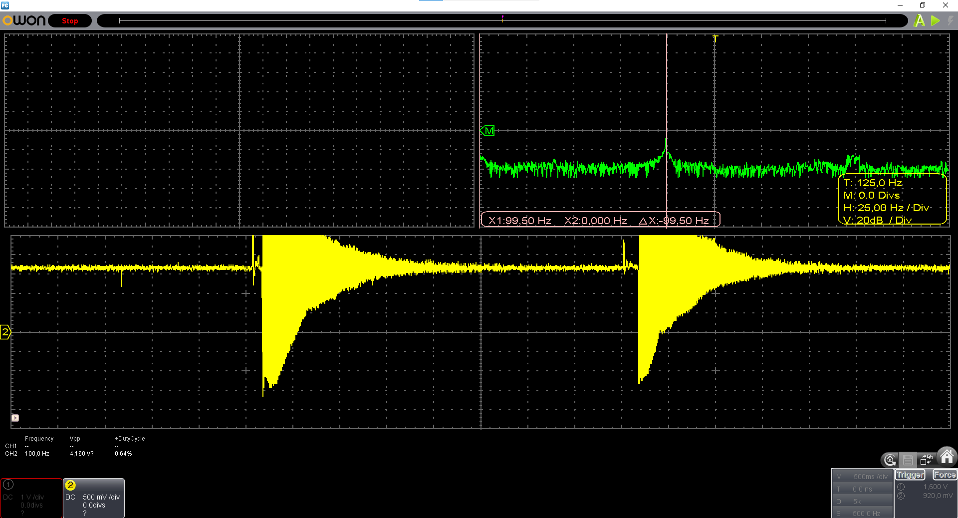
 It is very hard to really the correct frequency visually on the oszi. After Analyzing 111.mat it shows that the frequency was actually 111.3Hz.
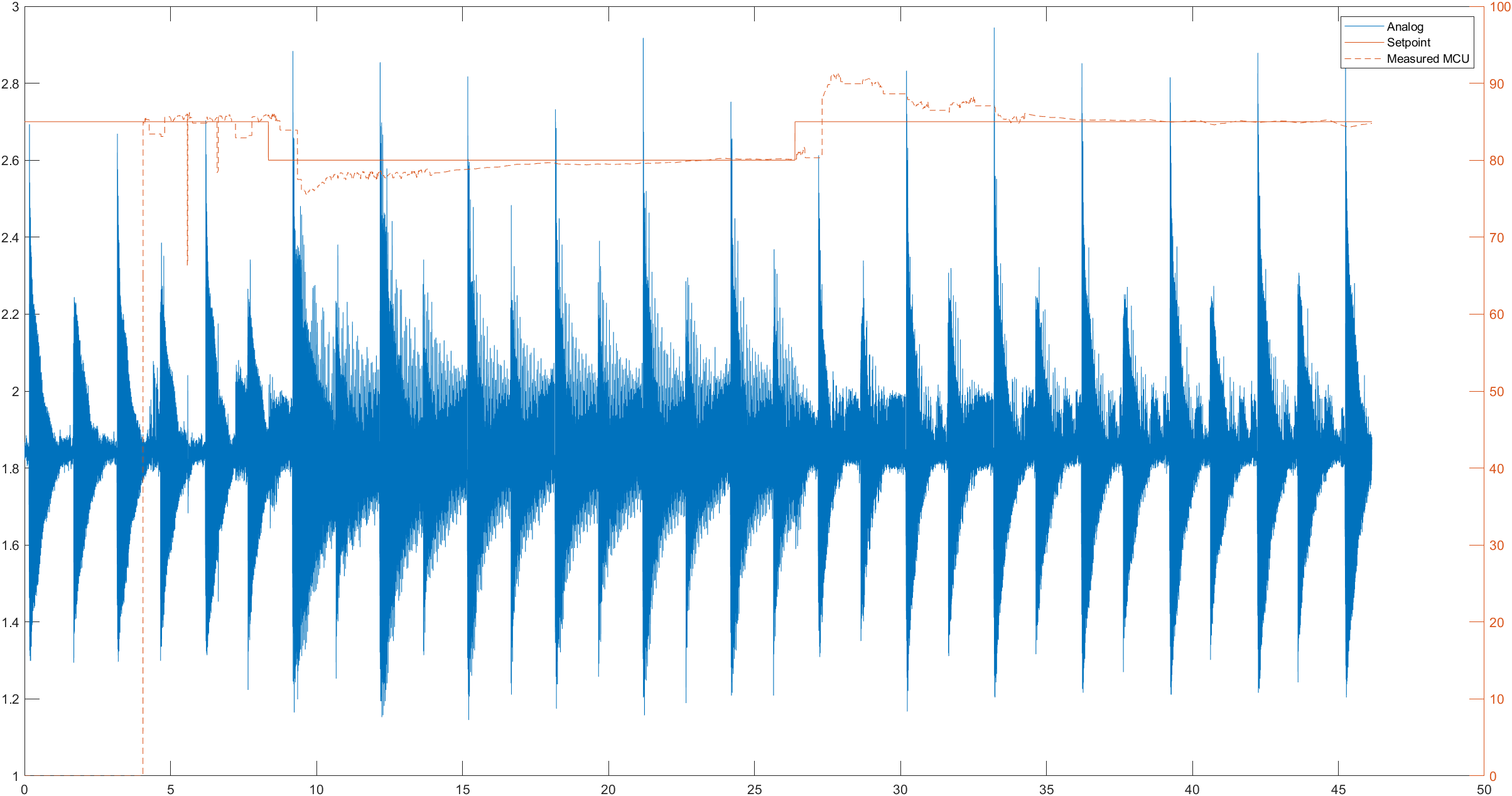 Data is available 85to80to85_analog_freq_setpoint.mat.
Using the Vaules after 35s. We can do the FFT like we did in Signal Acquisition.
Next to the roughly correct 85Hz signal we have a peaks at 50Hz and at multiples of it.
Data is available 85to80to85_analog_freq_setpoint.mat.
Using the Vaules after 35s. We can do the FFT like we did in Signal Acquisition.
Next to the roughly correct 85Hz signal we have a peaks at 50Hz and at multiples of it.
 After the setpoint change in 26.4 the motor seems to take some time to respond.
The motor kicks in immediately as shown below.
After the setpoint change in 26.4 the motor seems to take some time to respond.
The motor kicks in immediately as shown below.
 The ‘Determin Accuracy’ block is used to check if the error is in between . If so we use a PT-1 to smoothen our sensor Signal to get an average. There are no models used to adjust the control parameters yet. The Motor is not position controlled yet.
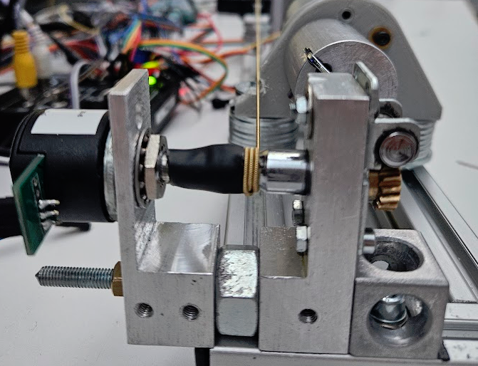 Let’s try to contorl the motor positon to the 1000th of a rotation. As you can see in Testing the Control loop there seems to be 50Hz noise on all lines. The noise here visible is not this noise it is vibration of the engine. I tried to get rid of the vibration. Nor P nor d nor I on it’s own were without vibration. This concludes that the vibration has to be taken into account. Dampeners??
 Jump from 0 to of a Revolution. The position contorl is stationary accurate!
Using a friction compesition is working. It is easier to just add a D part to the controller so the Motor is in movement most of the time. Friction is now negligible.
Jump from 0 to of a Revolution. The position contorl is stationary accurate!
Using a friction compesition is working. It is easier to just add a D part to the controller so the Motor is in movement most of the time. Friction is now negligible.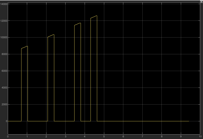 todo:
magnet anschliessen
und motor
platine löten
todo:
magnet anschliessen
und motor
platine löten